Introduction to Fresher Mechanical Design Engineer:
Entering the field as a mechanical design engineer as a fresher can be daunting, but with the right preparation, you can ace your interview and secure your dream job. Interviewers will assess your technical knowledge, problem-solving abilities, and how well you fit into their team. This guide provides a comprehensive list of 100 potential interview questions and model answers to help you prepare effectively.

General Questions for Fresher Mechanical Design Engineer:
1. Explain the design process as Mechanical Design Engineer you should follow for a new product.
Answer: The design process I follow includes identifying requirements, brainstorming ideas, creating initial sketches, developing CAD models, conducting simulations and analyses, prototyping, testing, and iterating the design based on feedback and test results.
2. What CAD software are you proficient in as Mechanical Design Engineer?
Answer: I am proficient in SolidWorks, AutoCAD, and CATIA. I have used these tools extensively during my academic projects and internships. (This Answer can be as per your Background and Career Goals)
3. How do you ensure the accuracy of your CAD models as Mechanical Design Engineer?
Answer: I ensure accuracy by double-checking dimensions and constraints, performing tolerance analysis, and using simulation tools to validate the design. Peer reviews and cross-verification with physical prototypes also help maintain accuracy.
4. What is FEA and how have you used it ?
Answer: Finite Element Analysis (FEA) is a computational method used to predict how a product reacts to real-world forces, vibration, heat, and other physical effects. I have used FEA in SolidWorks to analyze stress distribution in mechanical components and optimize the design for better performance and safety.
5. Can you explain the concept of GD&T as Mechanical Design Engineer?
Answer: Geometric Dimensioning and Tolerancing (GD&T) is a system for defining and communicating engineering tolerances. It uses symbolic language on engineering drawings to precisely describe the geometry and allowable variation of part features, ensuring consistency in manufacturing and inspection.
6. How should you perform a stress analysis on a component?
Answer: I perform stress analysis by creating a detailed CAD model of the component, defining material properties, and applying the relevant loads and boundary conditions. I then use FEA software to simulate the stresses and analyze the results to identify any potential failure points.
7. What factors should you consider when selecting materials for a design?
Answer: I consider factors such as mechanical properties (strength, hardness, ductility), thermal properties, corrosion resistance, cost, availability, and manufacturability. The intended application and operating environment also play a critical role in material selection.
8. Explain the difference between static and dynamic loads.
Answer: Static loads are constant or slowly varying forces applied to a structure, while dynamic loads vary with time and can include impacts, vibrations, and cyclic loads. Dynamic loads require consideration of factors like inertia and damping.
9. What are some common mechanical design principles you should follow as Mechanical Design Engineer?
Answer: Some common principles include designing for manufacturability, considering ease of assembly, ensuring proper tolerances and fits, optimizing for strength-to-weight ratio, and incorporating safety factors.
10. Explain the concept of fatigue in materials.
Answer: Fatigue is the progressive and localized structural damage that occurs when a material is subjected to cyclic loading. It can lead to cracks and ultimately failure of the material, even if the stress levels are below the material’s ultimate tensile strength. Understanding fatigue is crucial for designing components that are subject to repeated stress.
11. What is a factor of safety, and how should you determine it as Mechanical Design Engineer?
Answer: A factor of safety (FoS) is a design criterion that provides a safety margin by comparing the material’s strength to the expected loads. It is determined by dividing the ultimate (or yield) strength of the material by the maximum expected stress. The choice of FoS depends on the application, material properties, and the consequences of failure.
12. Describe the difference between stress and strain.
Answer: Stress is the force applied per unit area within materials, typically measured in Pascals (Pa). Strain is the deformation or displacement of material that results from an applied stress, expressed as a dimensionless ratio of the change in length to the original length.
13. What is thermal stress, and how can it be managed in a design?\
Answer: Thermal stress arises from the expansion or contraction of materials due to temperature changes. It can be managed by selecting materials with compatible thermal expansion coefficients, incorporating expansion joints, and designing for uniform temperature distribution to minimize differential expansion.
14. Explain the importance of heat treatment in materials.
Answer: Heat treatment processes, such as annealing, quenching, and tempering, alter the microstructure of materials to improve their mechanical properties, such as hardness, strength, and ductility. Proper heat treatment is crucial for enhancing the performance and longevity of mechanical components.
15. What is a kinematic chain, and how is it used in mechanical design?
Answer: A kinematic chain is a series of interconnected mechanical components, such as gears, links, and joints, that transmit motion and force. It is used to design mechanisms and machinery that perform specific tasks by converting input motion into the desired output motion.
16. How should you perform tolerance analysis in a design as Mechanical Design Engineer?
Answer: Tolerance analysis involves evaluating the acceptable limits of variation in dimensions and geometries of parts to ensure proper fit and function. I use tools like stack-up analysis, worst-case analysis, and statistical methods to determine the impact of tolerances on the overall assembly and performance.
17. Explain the concept of design for manufacturability (DFM).
Answer: DFM is a design approach that focuses on making products easy and cost-effective to manufacture. It involves considering manufacturing processes, material selection, and assembly methods during the design phase to reduce production costs, improve quality, and shorten time-to-market.
18. What is the purpose of a finite element model (FEM) in mechanical design?
Answer: A finite element model (FEM) is used to simulate and analyze the behavior of complex structures and components under various loads and conditions. It helps predict stress, strain, and deformation, allowing designers to optimize the design and ensure it meets performance requirements.
19. Describe the role of a design engineer in product lifecycle management (PLM).
Answer: A design engineer plays a crucial role in PLM by contributing to the product development process from concept to disposal. This includes designing, testing, and iterating the product, collaborating with cross-functional teams, ensuring compliance with standards, and supporting manufacturing and maintenance activities.
20. How do you ensure that your designs meet customer requirements?
Answer: I ensure designs meet customer requirements by thoroughly understanding their needs and specifications, involving them in the design process, and seeking their feedback at various stages. Regularly validating the design through prototypes and testing also helps ensure alignment with customer expectations.
22. What is the difference between SolidWorks and AutoCAD?
Answer: SolidWorks is a parametric 3D CAD software used for solid modeling, simulation, and design automation. AutoCAD, on the other hand, is primarily a 2D drafting tool but also supports 3D modeling. SolidWorks is generally preferred for complex mechanical design, while AutoCAD is widely used for architectural and engineering drawings.
23. Can you explain the use of PDM software in mechanical design?
Answer: Product Data Management (PDM) software is used to manage and control design data and documentation. It helps track revisions, manage versions, ensure data integrity, and facilitate collaboration among team members. PDM systems improve efficiency and reduce errors in the design process.
24. How do you perform a motion analysis in CAD software?
Answer: To perform a motion analysis, I create a detailed assembly of the mechanism, define the joints and constraints, and apply the necessary forces and motion inputs. I then use the software’s simulation tools to analyze the motion, study the kinematics and dynamics, and optimize the design for smooth operation.
25. What is the purpose of using simulation tools in design?
Answer: Simulation tools are used to predict the behavior of a design under various conditions without physical testing. They help identify potential issues, optimize performance, validate design assumptions, and reduce development time and costs by minimizing the need for physical prototypes.
26. Can you explain how you use CAM software in your designs?
Answer: Computer-Aided Manufacturing (CAM) software is used to generate toolpaths and G-code for CNC machining based on CAD models. I use CAM software to plan the manufacturing process, select appropriate tools, and simulate the machining operations to ensure efficient and accurate production of parts.
27. What is the role of 3D printing in mechanical design?
Answer: 3D printing, or additive manufacturing, allows for rapid prototyping and production of complex geometries that are difficult to achieve with traditional methods. It enables designers to quickly test and iterate their designs, reducing development time and costs while facilitating innovation.
28. How do you use parametric modeling in CAD software?
Answer: Parametric modeling involves creating CAD models that are defined by parameters and constraints, allowing for easy modification and updates. By changing the values of these parameters, I can quickly adjust the dimensions and features of the model while maintaining design intent and relationships.
29. Explain the concept of topology optimization.
Answer: Topology optimization is a computational technique used to determine the optimal material layout within a given design space to achieve the best performance under specified constraints. It helps in creating lightweight and efficient structures by removing unnecessary material while maintaining strength and functionality.
30. What is the use of assembly constraints in CAD software?
Answer: Assembly constraints are used to define the relationships and interactions between components in a CAD assembly. They ensure that parts are correctly positioned and aligned, allowing for accurate simulation of the assembly’s behavior and facilitating proper fit and function.
31. Describe your experience with any finite element analysis (FEA) software.
Answer: I have experience using FEA software like ANSYS and SolidWorks Simulation to analyze the structural integrity of designs. This includes setting up the model, defining material properties, applying loads and boundary conditions, running simulations, and interpreting the results to make informed design decisions.
32. What are the common types of materials used in mechanical design?
Answer: Common materials include metals (steel, aluminum, titanium), polymers (plastics, composites), ceramics, and composites. Each material has unique properties that make it suitable for specific applications based on factors like strength, weight, cost, and environmental resistance.
33. How do you select the appropriate manufacturing process for a design?
Answer: I consider factors such as material properties, design complexity, production volume, cost, and desired tolerances. I also evaluate the advantages and limitations of each manufacturing process, such as machining, casting, molding, and additive manufacturing, to select the most suitable one.
34. Explain the importance of material properties in mechanical design.
Answer: Material properties, such as strength, ductility, hardness, thermal conductivity, and corrosion resistance, determine how a material will perform under various conditions. Understanding these properties is essential for selecting the right material for a design to ensure its reliability, durability, and safety.
35. What are the differences between ferrous and non-ferrous metals?
Answer: Ferrous metals contain iron and are typically magnetic, with high strength and durability (e.g., steel, cast iron). Non-ferrous metals do not contain iron, are generally lighter and more corrosion-resistant, and include materials like aluminum, copper, and titanium.
36. Can you describe the injection molding process?
Answer: Injection molding is a manufacturing process used to produce parts by injecting molten material (usually plastic) into a mold. The material cools and solidifies into the shape of the mold cavity. It is widely used for producing high-volume, complex plastic parts with tight tolerances.
37. What is the difference between casting and forging?
Answer: Casting involves pouring molten metal into a mold to form a part, which is then allowed to cool and solidify. Forging, on the other hand, involves shaping metal by applying compressive forces using hammers or presses. Forged parts typically have higher strength and better grain structure compared to cast parts.
38. How do you ensure quality control in the manufacturing process?
Answer: Quality control involves setting clear specifications, conducting inspections, and using testing methods to verify that parts meet design requirements. I use tools like statistical process control, coordinate measuring machines (CMM), and non-destructive testing (NDT) to ensure consistent quality.
39. Explain the concept of heat treatment and its benefits.
Answer: Heat treatment involves heating and cooling metals in a controlled manner to alter their physical and mechanical properties, such as hardness, strength, and ductility. It is used to improve material performance, relieve internal stresses, and enhance wear resistance.
40. What are composite materials, and where are they commonly used?
Answer: Composite materials are made from two or more constituent materials with different properties, combined to create a material with enhanced characteristics. They are commonly used in aerospace, automotive, and sporting goods industries due to their high strength-to-weight ratio and durability.
41. Describe the role of surface finish in mechanical design.
Answer: Surface finish affects the appearance, performance, and functionality of a part. It influences factors like friction, wear resistance, and corrosion resistance. Achieving the desired surface finish is crucial for ensuring proper fit, sealing, and aesthetic quality.
42. What do you think is the future of mechanical design?
Answer: The future of mechanical design will likely be driven by advancements in digital technologies, such as AI and machine learning, which will enable more efficient and innovative designs. Sustainable design practices and the integration of smart materials and IoT technologies will also play a significant role.
43. How can mechanical design contribute to sustainability?
Answer: Mechanical design can contribute to sustainability by optimizing resource use, reducing waste, improving energy efficiency, and designing for recyclability. Using sustainable materials and considering the environmental impact throughout the product lifecycle are key aspects of sustainable design.
44. What role do you think 3D printing will play in the future of manufacturing?
Answer: 3D printing will play a significant role in the future of manufacturing by enabling rapid prototyping, customization, and the production of complex geometries that are not feasible with traditional methods. It will also facilitate decentralized manufacturing and reduce lead times and costs.
45. How do you stay innovative in your designs?
Answer: I stay innovative by continuously learning and exploring new technologies, materials, and design methodologies. Collaborating with diverse teams and seeking feedback helps generate fresh ideas. I also follow industry trends and best practices to inspire and inform my work.
46. Describe a time when you implemented a new technology or method in a project.
Answer: In a university project, I introduced topology optimization techniques to design a lightweight yet strong component for a drone. This approach led to significant weight reduction without compromising structural integrity, demonstrating the potential of advanced computational methods in design.
47. What are some emerging technologies in mechanical design that excite you?
Answer: Some emerging technologies that excite me include additive manufacturing, AI-driven design optimization, smart materials, and digital twin technology. These innovations have the potential to revolutionize the way we design, test, and manufacture products.
48. How do you think automation will impact mechanical design and manufacturing?
Answer: Automation will streamline design and manufacturing processes, improve precision and consistency, reduce human error, and increase productivity. It will also enable more complex and efficient designs by leveraging advanced robotics and AI-driven tools.
49. What are engineering tolerance?
Answer: Engineering Tolerances are allowable variation from given dimensions. In other words, it is the total amount by which a given dimension may vary without affecting product function.
Tolerance (for hole) = Hole (MMC) – Hole (LMC)
50. Why Tolerance are Required?
Answer: The production of closely mating parts, without tolerances is economically unfeasible. This will increase the rejection rate and manufacturing cost. Therefore, tolerances are used with part dimensions to facilitate manufacturer and reduce cost.
51. What is tolerance Stack-up Analysis?
Answer: Tolerance Stackup analysis is a design tool used to analyse and optimize product assembly. It calculates the cumulative effects of part tolerances in an assembly.
52. What are the types of tolerance?
Answer:
- Unilateral Tolerance
- Bilateral Tolerance
53. What do you understand by fit?
Answer: The term fit refers to the permissible clearances between mating parts. The clearance between mating parts determines the type of Fit.
54. What are the different types of fits?
Answer:
- Clearance Fit
- Interference Fit
- Transition Fit
55. What do you understand by Engineering Drawing?
Answer: Engineering drawing is a technical document used to transfer technical information and define requirements. In other words, it’s a graphical language that communicates ideas and information from one mind to another.
56. What is Section, Projection, Isometric & Detailed View?
- Projection View : Projection view represents a 3 dimensional objects in 2 dimensions while looking from one side.
- Section View: It is used to show the interior construction of a part in engineering drawing.
- Isometric View: Isometric projection represents a 3D objects into 2D in an engineering drawings. In this three coordinate axes appear equally foreshortened and the angle between any two axes is 120 degrees.
- Detailed View: It represents the larger view of any section of engineering drawing.
57. What is the symbol of 1st and 3rd angle projection?
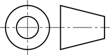
FIRST ANGLE VIEW
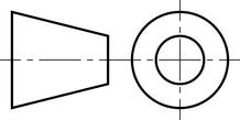
THIRD ANGLE PROJECTION
58. Which projections are preferred for engineering drawings?
Answer: Following two types of projections are used :
- First Angle Projection
- Third Angle projection
59. What is least count and how it is calculated?
Answer: It is the smallest value measured with the measuring instrument. For example, least count for a normal scale is 1 mm whereas for vernier scale it is 0.01 mm.
Least Count= Value of one main scale Division – Total Number of Vernier scale division
60. What is least count for Vernier Scale, Micrometer and normal scale
Answer:
- Vernier Caliper Least Count = 0.01 mm (Digital) , 0.02 mm (manual)
- Micrometer Least Count = 0.01 mm
- Normal scale Least Count = 1 mm
61. What is factor of safety and how it is calculated
Answer: FOS describes the load carrying capacity of a system beyond the expected or actual loads. In another words, FOS represents : how much stronger the system is compared to intended load.
FOS is calculated considering design load maximum value. Value of FOS is always greater than one.
62. What are types of screws?
Answer: Screws can be classified based on following parameters:
Based on Screw Head
- Counter Sunk Screw
- Raised or oval head screw
- Pan Head Screw
- Flat Head Screw
- Flange Head Screw
Based on Screw Drive Type
- Slotted
- Phillip
- Pozi Drive
- Torx Head
- Hex Socket
- Trangular head
- Security Head Socket
Based on Screw Thread Type
- Machine Screw
- Thread Forming
- Thread Cutting Screw
63. What is datum plane?
Answer: A datum is theoretical exact plane, axis or point location that GD&T or dimensional tolerances are referenced to.
64. What is GD&T (Geometric Dimension & Tolerance) ?
Answer: GD&T is a system for defining engineering tolerances. It helps in conveying product assembly requirements to manufacturer. Geometric dimension and tolerance ( GD&T ) is a system to define nominal and allowable variations in part and assembly geometry. They are used along with linear tolerance. ASME Y14.5-2009 standard has defined GD&T symbols in detail.
65. Why GD&T is Required?
Answer: To ensure manufactured part quality. It is necessary to communicate design and assembly requirements in drawing. Geometric dimension and tolerance helps in accurately defining part geometry requirements.
GD&T allows comparatively larger tolerance zone. Therefore part rejection rate and cost also decreases.
66. Types of Geometric Dimension and Tolerance
Answer: Five types of GD&T tolerance are used to define a part design intent accurately. This includes 14 symbols that controls the features and geometry of a part.
- Form Control
- Profile Control
- Orientation Control
- Location
- Runout
If you want to add some questions after finishing your interview as Mechanical Design Engineer, please put your comment. This shall help many other candidates who might face the same questions and can crack the interview at the very first time. Hence we always say that “READ IT !!!! CRACK IT!!!!
You can also further read on other topics related to Interview of mechanical engineer here.